
Automating Sloping Driveways in Lewes and the South Downs
Sloping driveway in Lewes or the South Downs? See how foundations, drainage and track design decide which gate automation clears the ground.
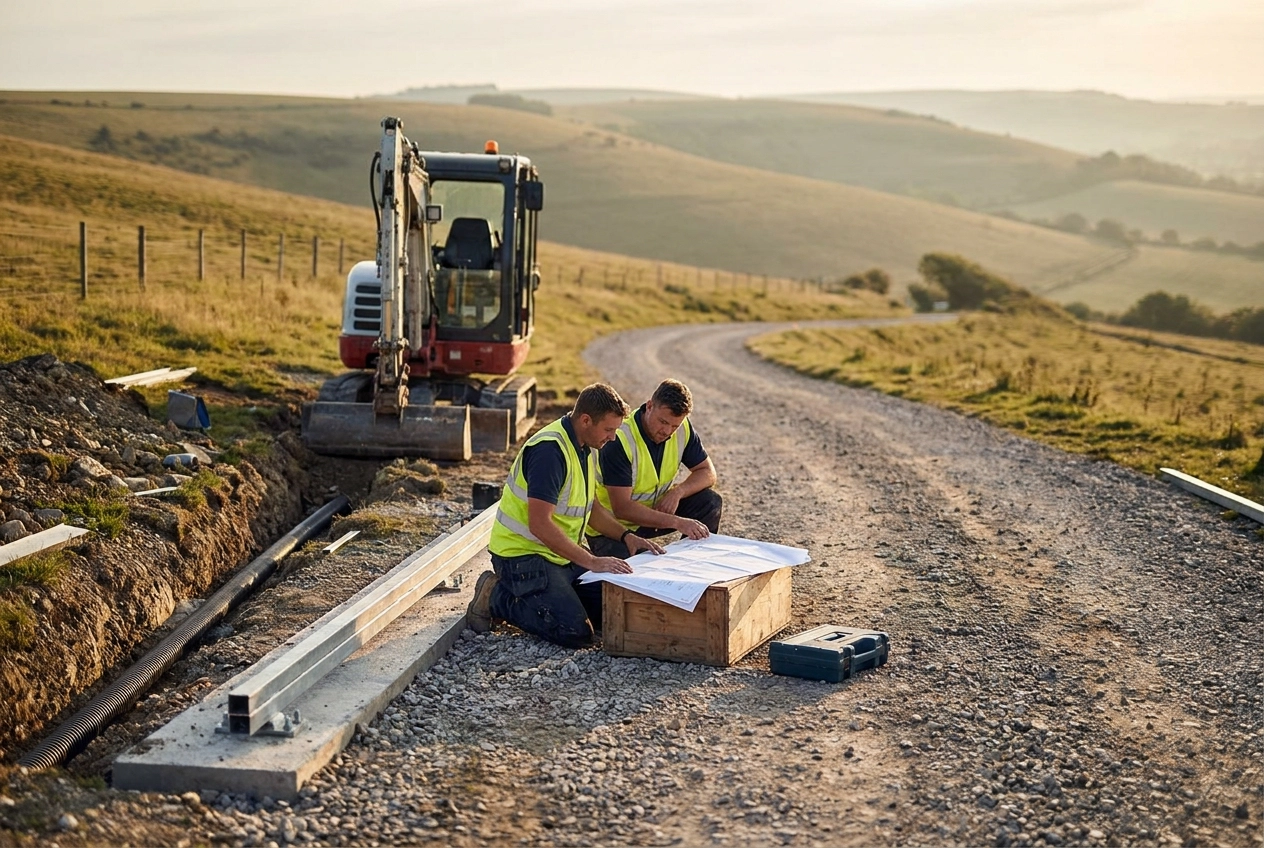
On a sloping driveway in Lewes or the South Downs, the gate is rarely the hard part. The gradient, cross-fall, and chalk drainage decide the specification long before gate style enters the conversation. That is the core principle behind reliable driveway gate automation on graded ground: what happens underneath the gate matters more than the gate itself. A sliding gate that cannot run back, a swing operator fighting gravity, or a track sitting in collected runoff will scrape, flood, or stall no matter how well the gate is made.
This tutorial treats the terrain as the brief. We will work through why the ground sets the specification; what a site survey must record before any gate is chosen; foundation and track design on graded ground; drainage channels and runoff control; and the underground changes chalk ground brings on the South Downs. From there, we will compare sliding and cantilever gates as the default on a gradient, assess when swing gates still work with rising hinges and above-ground operators, and cover operator torque, manual release safety, wiring, electrics, and flood exposure. The conclusion is simple: specify the ground first, then the gate.
Why the Ground Sets the Specification on a Sloping Driveway
A swing gate leaf sweeps through an arc that changes height across the opening, so clearance under the leaf varies along the travel path rather than staying constant. That is a ground problem, not a gate style problem.
A sliding or cantilever gate travels along the fence line instead of sweeping across rising ground. This removes the clearance issue at the opening but creates a different requirement: side run-back room beside the entrance. Our sliding gate vs swing gate comparison covers the trade-offs.
Any operator for electric gates for driveways has to start and stop against gravity it would not face on level ground, so duty rating and torque matter more on a gradient than a simple gate weight figure.
The real specification on a sloped driveway is the layer you cannot see: foundation depth, track bed, travel path and drainage. Get those wrong and no gate type rescues the installation. Work in order. Choose the ground solution first and the gate second. Reversing it is how installations end up scraping at one end of travel, flooding at the low point or stalling under load. Treat driveway gate automation on a slope as an engineering brief with a gate attached, not a gate purchase with a delivery address.
What a Site Survey Must Record Before Any Gate Is Chosen
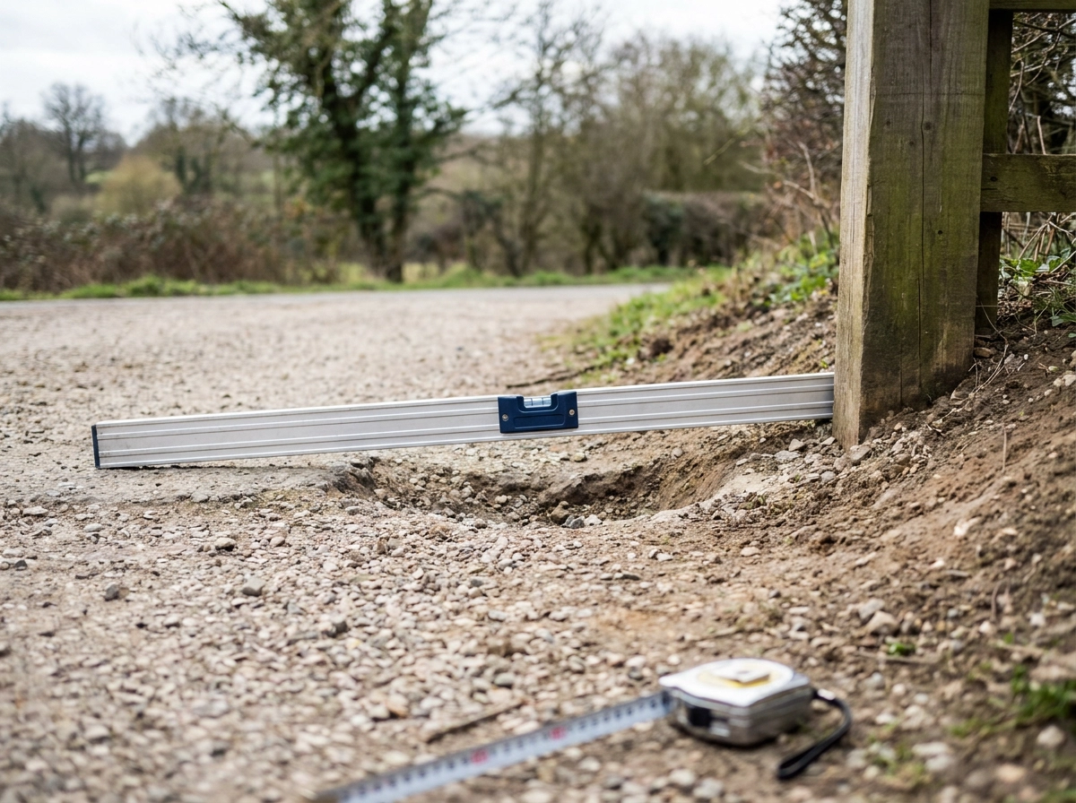
The survey begins where the ground does. Record driveway width, longitudinal slope, cross-slope and the grade change on both sides of the opening. That grade change at the gateway, not the average gradient of the drive, is usually what decides the specification.
Map the travel path next: where the leaf, the track or the cantilever counterweight sits at full travel, where the run-back falls, and where end stops land. Locate buried services, existing drainage runs and any soakaway before excavation begins, and note vehicle turning needs at the top and bottom of the slope.
Runoff matters. Identify where water naturally collects; on a sloping drive the low point is normally where water, moving parts and electrical equipment all end up together. If you are comparing electric gates near me search results, a practical decision framework helps: ask whether the quote came from a surveyed gradient or an estimate based on a photo and a postcode. Electric gate installation on a gradient should begin with measurements, not a catalogue. A survey should also note access for plant, concrete and delivery vehicles, because a restricted South Downs entrance changes how the ground solution is built, not just how it is drawn. With those measurements in hand, the foundation design can follow.
Ask every installer whether the quote derives from a recorded survey of those measurements, not from a photo and a postcode.
Foundation and Track Design on Graded Ground
Foundation design follows the survey as the first engineering decision. Tracked sliding gates suit entrances excavated and finished to a consistent level along the run; without that datum, the track bed flexes and the leaf drags.
Trackless cantilever gates are supported at one end, so the footing beneath that post carries the full leaf and cantilever arm. It is sized to the gate, not copied from a standard drawing; HSE requires foundations to resist the dynamic forces of the moving gate and wind loading.
On a graded drive, the gate runs on a level foundation section while the drive rakes away above and below it. Separating the gate line from the drive's gradient is what stops the leaf scraping ground it should clear. Gate Safe notes sliding gates need a flat roadway width and run-back.
A raised foundation lifts the mechanism clear of surface water, but only if approach, drainage and sight lines are planned together. Concrete depth, reinforcement and preparation follow what is under the surface, so fabrication follows the survey. A cracked track bed or settled cantilever footing costs far more to correct than choosing one gate style over another. Where ground is inconsistent, the money belongs in the foundation. Budget for the ground layer first, hardware second.
Drainage Channels and Runoff: Keeping Water Away From Moving Parts
Drainage is the second ground decision after the foundation, and belongs in the survey, not the aftermath. Runoff must not collect near moving parts, gate posts or the control cabinet, so plan the drainage line before the gate layout, not after the concrete has cured.
A channel or slot drain across the entrance, or at the low point, intercepts water before it reaches the track, the parked position or a pillar base. Runoff on a gradient has less distance to travel to the low point, so drainage at the entrance must cope with flow that arrives quickly; size and position the drain for that reality, not for a flat-drive assumption.
The channel's route matters as much as its capacity. A drain the leaf or cantilever counterweight passes over must stay flat and load bearing under vehicle wheels, clear of the travel path.
Wiring needs the same care. Gland type, conduit routing, joint positions and cabinet height are drainage decisions as much as electrical ones, and the same logic governs keypads and intercoms, as set out in our guide to power, cabling and connectivity on site.
Raising one component does not make an installation flood resistant. Flood exposure, elevation, drainage, gate movement, electrical equipment and access are one system; treating them separately leaves a gap water will find.
Chalk Ground and the South Downs: What Changes Underground
That runoff meets ground that is far from uniform. Chalk can drain freely in one spot and hold water in fissures, solution hollows or old pipework a few metres away, so a generic rule about drainage on chalk is not a specification.
Flint bands and shallow topsoil over chalk affect how deep excavation can go and how a foundation or track bed must be adapted; the BGS record of distinct flint horizons and marl seams in South Downs chalk means ground conditions should be confirmed by on-site investigation before any foundation is sized.
On South Downs terrain, runoff needs a defined route out rather than an informal soakaway. Published geology for the Downs is a useful starting point, but ground conditions must be confirmed on site. A survey on the actual drive is what protects the installation.
Discharge points, soakaway design and any consent for water leaving the property should be checked with the relevant local authority during planning, not assumed from a generic guide.
Chalk and slope together explain why a Lewes or South Downs entrance so often needs drainage designed as part of the gate specification rather than added by a landscaper afterwards.
Sliding and Cantilever Gates as the Default on a Gradient
With ground conditions understood, gate type becomes a resolution rather than a starting point. For a general comparison, see Swing Gates vs. Sliding Gates: Which Design Suits Your Driveway?.
A cantilever gate carries its own leaf on a counterbalanced arm, so it needs no track across the opening and no ground clearance beneath the moving leaf. That is why it copes more comfortably with uneven or rising ground than a swing gate. A tracked sliding gate works well where the entrance can be excavated and finished to a consistent level along the run, but the track is only as good as the bed beneath it.
Both types need clear side run-back. On a constrained South Downs entrance, available run-back can rule out a sliding gate regardless of how well it handles the slope.
The foundation and drainage do the work, not the gate type. The operator must be specified against the measured gradient, the leaf weight and the manufacturer's stated duty rating; the gradient at the run-back is a key input, not a detail to resolve on site. End stops, buffers and a defined travel path matter more on a slope, where the leaf carries momentum it would not have on the flat.
When a Swing Gate Still Works: Rising Hinges and Above-Ground Operators
Where no run-back exists for a sliding leaf, a swing gate remains viable if it is engineered to climb rather than scrape. Mechanically, a rising hinge raises the leaf as it opens, so it clears ground that rises across its arc instead of digging into it, this is the principle behind rising hinges, which should be selected and set from survey measurements of the pivot height and the ground profile. They suit narrow openings between walls, banks or established planting, where a cantilever beam and its counterweight will not fit.
The most common failure is the leaf striking the ground at one end of its travel. Hinge geometry, pivot heights and stop positions must be derived from the survey rather than adjusted on site. Operators for swing gates on a grade must be specified to move a leaf that gravity is working against throughout the arc; the installer should confirm the operator's torque rating against the surveyed gradient and the leaf weight, not assume a flat-drive spec will suffice. Where water collects in low spots, an above-ground operator avoids the drainage risk that a below-ground housing creates; confirm the drainage picture before committing to an operator mounting method.
Before committing to a gate width, check the swept arc at both ends of the drive, including clearance over the rising side. A leaf that clears one post and fouls the other is a width problem, not a hinge problem.
Operator Choice, Torque and Manual Release Safety on a Slope
Whichever gate type the survey supports, the operator must start and stop the leaf against gravity, and a graded run leaves less margin for error than a flat one. Heavy duty units reduce stress on the motor, the gearbox and the drive train.
Ignore unsourced marketing claims that a gate feels a set number of times heavier on a slope, because no verified figure exists. What matters is the measured gradient, the leaf weight and the operator's duty rating.
Manual release is a safety matter on a gradient. When a gate is released manually on a slope, gravity acts on the leaf; the release method must account for this and should be agreed at design stage.
Powered gate safety duties in the UK, including entrapment protection, force limitation and warning signage, should be checked against current official guidance and built into the specification before installation, so safety comes as standard rather than being retrofitted.
Specify the stopping and holding arrangement with the gate itself: end stops, braking and any hold-to-run behaviour, agreed at design stage rather than added after a problem appears.
Wiring, Electrics and Flood Exposure on a Sloped Drive
With the operator and its release method settled, the buried layer needs equal scrutiny.
Power and control wiring on a sloping driveway is usually buried where surface water runs. Conduit routing, burial depth and joint positions should follow the drainage plan, not the shortest line to the gate.
Site the control cabinet above the likely flood level and away from the low point of the drive, with a mounting height that keeps cable entries out of any ponding.
Intercoms, keypads and safety devices must be reachable from a vehicle stopped on a gradient. A position that works on flat ground rarely does here.
The same whole-system logic that applies to drainage applies equally to the electrical layer. Similar placement considerations apply to frequently asked questions about bifold driveway gates.
A gate that operates reliably in dry conditions but faults after heavy rain is more likely to have a drainage or water-ingress issue than an electronics fault; this is a reason to treat the drainage design as part of the electrical specification.
Specify the Ground First, Then the Gate
With wiring and drainage settled as one system, the sequence of decisions should be equally deliberate. Choose the ground solution first: foundation design, track or trackless running, travel path, run-back and drainage. Only once that layer is settled should gate type be chosen. Reversing this order is how installations end up scraping, stalling or flooding.
On a Lewes or South Downs property, ask specifically how the installation will handle chalk, runoff and the low point of the drive. That answer separates a considered quote from a copied one.
Conclusion
On a sloping driveway in Lewes or the South Downs, the ground sets the specification. A site-specific survey, recording slope, cross-slope, grade change, travel path and services, is the only route to a specification the ground will accept. The sequence is the same on every sloping drive: survey the ground, design the foundation and drainage, then choose the gate.