
Gate Post Installation for Electric Gates: Why the Foundation Determines Everything
Electric gate post installation: foundation design, concrete specs, depth requirements, and why correct footings prevent costly remedial work.
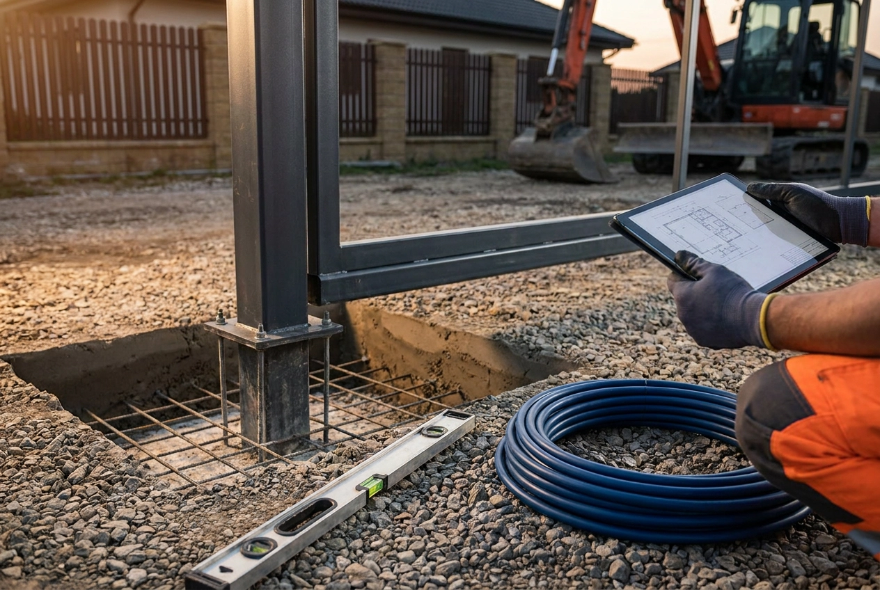
Most homeowners investing in electric gates spend considerable time selecting the right automation system, choosing between swing and sliding configurations, and debating aesthetic finishes. Very few think carefully about what happens underground. That oversight is costly.
Gate post installation is the structural foundation of every automated gate system, and it is where long-term performance is either secured or quietly compromised. A perfectly specified motor, a premium control panel, and high-quality ironwork will all underperform if the posts holding them are inadequately founded. Continuous automation cycles generate mechanical stress that static fence posts never experience, and that stress transfers directly into the ground with every open and close cycle.
This analysis works through the variables that govern correct post footing design: foundation depth relative to frost line, concrete specification, post material and sizing, wind loading, and the iterative calculations that bring these factors together. It also addresses the remedial costs that follow when foundations are underspecified, and what questions to ask your installer before a single spade breaks ground. Understanding these principles before work begins is significantly cheaper than correcting them after the automation is fitted.
Why Electric Gates Demand More Than Standard Fence Posts
A standard fence post has one structural job: resist the wind. It bears a passive, largely predictable lateral load and nothing more. Electric gates impose an entirely different set of demands, and treating the two as equivalent is where long-term installation failures begin.
Every automation cycle, whether a swing or sliding panel, applies a directional mechanical stress to the post and its footing. A residential gate opening and closing several times daily accumulates thousands of these stress events each year. Generic fence installation guidance does not model cyclic loading of this kind; it is engineered for structures that stay still.
The load profile is further complicated by the equipment mounted to the posts. Motor housings, access control panels, and intercom columns all add distributed weight beyond the gate panel itself. Electric driveway gates designed for vehicle access typically span three to five metres, presenting a wind area that dwarfs a standard fence panel. That panel becomes a sail; the post is the mast anchor, reacting substantial lateral forces on every exposed or gusty day.
What makes undersized foundations particularly deceptive is the failure mode. There is no sudden collapse. Instead, the post settles progressively, loses plumb by fractions of a millimetre per month, and the gate begins to hang fractionally out of alignment. The motor compensates, then strains, then degrades. By the time the fault is diagnosed, the root cause is buried in concrete beneath the installation.
The Four Variables That Govern Post Footing Design
Those structural demands translate into four discrete engineering variables, each of which must be correctly specified before a single bag of concrete is mixed.
Depth is the primary lever. Soil lateral bearing pressure increases proportionally with embedment depth, meaning a deeper footing resists horizontal forces more efficiently than a shallower, wider one. For an electric gate post absorbing repeated motor torque loads, depth is non-negotiable.
Footing diameter must exceed the post diameter by a minimum of 4 inches. For square or rectangular hollow sections, that clearance applies to the diagonal corner-to-corner dimension, not the face width. Measuring from the flat face understates the required excavation and leaves inadequate concrete coverage at the corners.
Concrete specification is fixed, not flexible. A minimum compressive strength of 2,000 psi is required, with a slump of 4 to 6 inches to ensure the mix flows fully around the post base without voids. Only ready-mix concrete reliably achieves both parameters on site; bagged mixes with inconsistent water ratios cannot.
Soil bearing capacity varies materially by ground type. Clay-heavy soils, common across parts of East Sussex and Kent, retain water and undergo seasonal expansion and contraction. That movement demands deeper footings than free-draining sandy or gravelled ground would require under identical gate loads.
Critically, these variables interact. A shallower footing may require a larger diameter to compensate; a deeper footing in competent soil may permit a reduced concrete volume. No single variable can be optimised without reassessing the others.
Footing Depth, Frost Line, and Why Two Feet Is Rarely Enough
Footing depth is where the variable interaction explored in the previous section becomes most consequential in practice.
The 2-foot minimum depth cited in general installation guidance applies to light static fence posts in favourable, free-draining ground. It is not a transferable baseline for an electric gate post, which carries dynamic loads across thousands of automation cycles. Applying that figure to a motorised gate is a category error.
The correct starting point is the local frost line, not an arbitrary depth rule. Footings must extend at least 6 inches below the frost penetration depth, because frozen soil expands laterally and vertically. A post founded within the frost zone is progressively levered by this expansion cycle, losing plumb incrementally over successive winters.
In the UK, frost depths are shallower than North American benchmarks, but they are not negligible. Ground frost in East Sussex and Kent can penetrate to 300-450mm in a severe winter. A footing terminating within this zone will eventually move, regardless of how well the concrete was poured.
Gate weight compounds the problem in a specific way. Vertical load from a heavy automated panel acts downward through the post; frost heave forces act laterally and perpendicular to that load. A marginally deep post cannot resist both simultaneously, and the result is progressive loss of plumb rather than straight-down settlement.
The practical implication is straightforward: treat the frost-line minimum as a floor, not a target. An additional 150-200mm of depth costs very little in concrete at installation. After automation equipment is fitted, remedial groundwork costs multiples of that saving.
Concrete Specification: Why Ready-Mix Is Not Optional
Depth alone does not make a footing structurally sound. Once the excavation is correctly sized and positioned, the concrete specification determines whether that depth delivers lasting performance or simply buries the problem deeper.
In-situ mixed concrete and dry-tamped post mixes cannot reliably achieve the 2,000 psi minimum compressive strength required for gate post footings. The failure mechanism is not dramatic; it is statistical. ACI 301-20 acceptance criteria allow approximately 10% of individual strength tests to fall below the specified value, and that tolerance is premised on certified producers, controlled water-to-cement ratios, and laboratory testing. Site-mixed concrete has none of those controls. Inconsistent hydration and variable aggregate distribution mean final strength is genuinely unpredictable, not merely slightly lower.
Workability matters equally. A slump of 4 to 6 inches ensures the mix flows into the full excavation and consolidates around the post base. A stiffer mix may look solid at the surface but can conceal voids beneath. Those voids concentrate stress and initiate cracking under the repeated loading that electric gate automation delivers with every cycle.
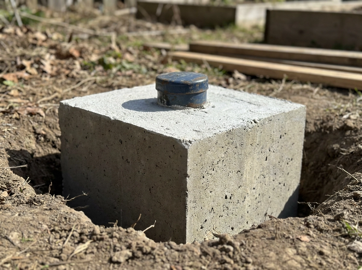
Finishing the pour correctly is the third variable. Bringing concrete approximately 12mm above ground level and sloping the surface away from the post creates a drainage collar that sheds water from the post-to-concrete interface. This matters most for steel posts, where that interface is the primary site of ground-level oxidation. Galvanising and powder coating provide meaningful protection above the collar, but neither is reliable under sustained moisture at the soil contact zone.
All of this is irreversible once buried. There is no way to assess footing quality after an automatic gate installation is complete without full excavation.
Post Material and Sizing for Automated Gate Loads
The concrete foundation anchors the post; the post itself must be equally well specified.
Steel hollow section is the standard post material for electric gate installations for good reason: it combines a high strength-to-weight ratio with the ability to accept welded motor mounting brackets directly, and it resists the lateral loads that automation equipment generates in a way that timber or solid-bar alternatives cannot match.
Section size must be proportionate to gate weight and span. A 3-metre, 200kg swing gate demands a materially larger hollow section than a lightweight pedestrian gate. Undersizing the post does not simply weaken it; it transfers excess stress into the footing, accelerating the cracking and settlement the concrete specification is designed to prevent.
Wall thickness is equally critical and often overlooked. A thin-walled section may meet the correct external dimensions but flex under motor torque, introducing micro-movement at the footing interface. That movement is cumulative; over thousands of automation cycles it progressively loosens the concrete bond.
Where motors are column-mounted rather than ground-mounted, the post carries additional load: the full motor housing weight plus reactive torque from every operation. This transforms the post from a purely structural element into a composite structural and mechanical component. Before choosing a motor type or drive configuration, the post section should already be sized to accommodate it.
Reviewing the distinctions between drive options before the post is specified avoids the common error of treating post selection and motor selection as separate decisions made at different project stages.
Wind Loading: The Variable Most Installers Underestimate
Post sizing accounts for forces within the gate system itself, but not what weather imposes from outside.
A solid infill gate panel spanning 3 to 5 metres presents a substantial surface area to moving air. Unlike a fence panel broken by posts at regular intervals, a vehicle gate is a largely uninterrupted plane. At typical UK wind speeds, the lateral force on a closed solid gate in an exposed position is considerable, acting as a continuous horizontal load transmitted directly into the post footing.
This is not an edge case. For rural and coastal properties across East Sussex and West Sussex, sustained wind pressure on a large gate panel is a routine operating condition.
The direction of that load matters. Depending on which way wind strikes relative to the hinge axis, the force acts to open the gate, drive it harder onto its stops, or introduce a twisting moment. In every case, the reactive force travels through the post and into the footing. A foundation sized for gate weight alone may be inadequate once wind load is added.
Panel choice directly affects this. Open-infill designs, such as vertical bar or railing styles, allow air to pass through and reduce wind loading significantly compared to solid or close-mesh panels. Where footing depth is constrained by services, rock, or groundwater, choosing between swing and sliding configurations and selecting an open-infill panel style becomes a structural decision, not purely an aesthetic one.
Any installer quoting for electric gate installation who has not assessed site exposure and panel wind area has not properly scoped the foundation.
The Cost of Getting It Wrong: Remedial Groundwork After Installation
Wind loading failures are dramatic when they occur, but the more insidious foundation failures develop quietly, over months, as a post settles a few millimetres off plumb.
When that happens after a fully operational electric gate system is in place, the remediation sequence is costly. Automation equipment must be disconnected and removed, the gate lifted from its hangings, and the post either excavated and re-founded in situ or extracted entirely before any corrective work can begin. Each stage carries its own labour cost. Together, they multiply what the correct foundation specification would have added at the outset.
The diagnostic problem compounds the expense. Post settlement is routinely misdiagnosed as motor or control board failure. Service engineers are called out, components are replaced, and adjustments are made, all charged at standard rates, against a problem that is structural, not electrical. Until the post is properly re-founded, the fault will return.
Even modest plumb deviation changes how the gate panel hangs. The load shifts from the designed bearing points on hinge pins and motor drive mechanisms onto surfaces not rated for asymmetric stress. Wear accelerates on components that were specified for aligned, balanced operation. If you have ever considered retrofitting an existing manual gate with automation, this is precisely why foundation assessment must precede any automation decision.
At Portara Automation, post specification and footing design are addressed during the initial survey, treated as a structural engineering decision. The incremental cost of correct depth, concrete grade, and post sizing is modest relative to total project cost. The cost of not getting it right is not.
What to Ask Your Installer Before Work Begins
Knowing the right questions to ask puts you in a far stronger position to evaluate any quote for electric gate installation before a single hole is dug.
Ask how footing depth has been calculated. A competent installer should reference gate weight, local soil conditions, frost depth, and site wind exposure. If the answer is a uniform figure applied to every job regardless of circumstances, that is a signal the foundation has not been individually assessed.
Confirm the concrete specification. Ready-mix concrete to a minimum of 2,000 psi compressive strength is the correct standard. Bagged post mix tamped dry into the excavation cannot achieve consistent strength or the 4-to-6-inch slump needed to eliminate voids around the post base.
Ask whether post sizing and automation equipment have been specified together. Posts and motors selected independently by different parties is a common error on general contractor projects; for a properly functioning electric gate system, they are a single integrated decision.
For large panels, vehicle gates, or exposed sites, ask whether wind loading has been assessed. Sites across East Sussex, West Sussex, and Kent vary considerably in exposure, and a quote that ignores wind area has not fully scoped the foundation. Choosing between solid and open-infill panel styles, for instance, is worth understanding early. The guidance on making the right choice for your property covers this in more detail.
Finally, request written documentation. Footing dimensions, concrete specification, and post section sizes should appear in the installation scope. If an installer cannot provide this, it reflects directly on how thoroughly the foundation has been considered.
Foundation First: The Principle That Protects Every Part of the System
The questions in the previous section are worth asking because the answers reveal whether a given installer treats the foundation as an engineering decision or an afterthought. The principle underlying all of them is the same: every component above ground, the motor, gate panel, access control hardware, and hinge geometry, depends entirely on the post staying plumb and stable under sustained, repeated mechanical load.
The specifications are not arbitrary. Ready-mix concrete to a minimum of 2,000 psi compressive strength, a footing diameter at least 4 inches beyond the post section, depth extending at least 6 inches below the local frost line, and a concrete collar sloped away from the post base: each requirement addresses a distinct failure mechanism. Remove any one of them and a different failure mode opens.
The cost logic is equally straightforward. Correct foundation work at installation adds a modest increment to project cost. Remedial groundwork after an electric gate system is operational, requiring the automation to be disconnected, the gate stripped from its hangings, and the post re-founded or extracted, costs multiples of that saving. The foundation is the only part of the installation that cannot be sensibly revisited later.
Specialist design-and-install providers integrate structural and mechanical decisions from the first site visit. If you are planning an automatic gate installation and want that integration from the outset, making the right choice for your property starts with the right survey. Portara Automation offers installation scoping and site surveys across East Sussex, West Sussex, and Kent; contact us to discuss your project.
Conclusion
Electric gate foundations are not a detail to be negotiated down. They are the single decision that determines whether every component above ground performs reliably for years or fails prematurely under mechanical stress. The key principles are clear: depth must exceed the local frost line, concrete specification is non-negotiable, post sizing must reflect actual gate weight and wind loading, and remedial work after installation costs far more than doing it correctly the first time.
Every automated gate system is only as dependable as the ground it stands in. Choosing an installer who integrates structural and mechanical planning from the first site visit protects your investment at every level.
If you are planning an electric gate installation in East Sussex, West Sussex, or Kent, start with a professional site survey. Contact Portara Automation to discuss your project and get the foundation right before anything else goes in the ground.